Building a dataflow in Cloudera Edge Management
You can build an automated dataflow using the Edge Flow Manager UI in Cloudera Edge Management. Simply drag components from the toolbar to the canvas, configure the components to meet specific needs, and connect the components together.
For additional information about flow creation and related concepts, check out the video on the Cloudera Edge Management YouTube playlist:
Adding components to the canvas in Cloudera Edge Management
Learn how to add each of the components available in the Components
Toolbar in the Edge Flow Manager UI. You can add processors, remote
process groups, and funnels.
Processor
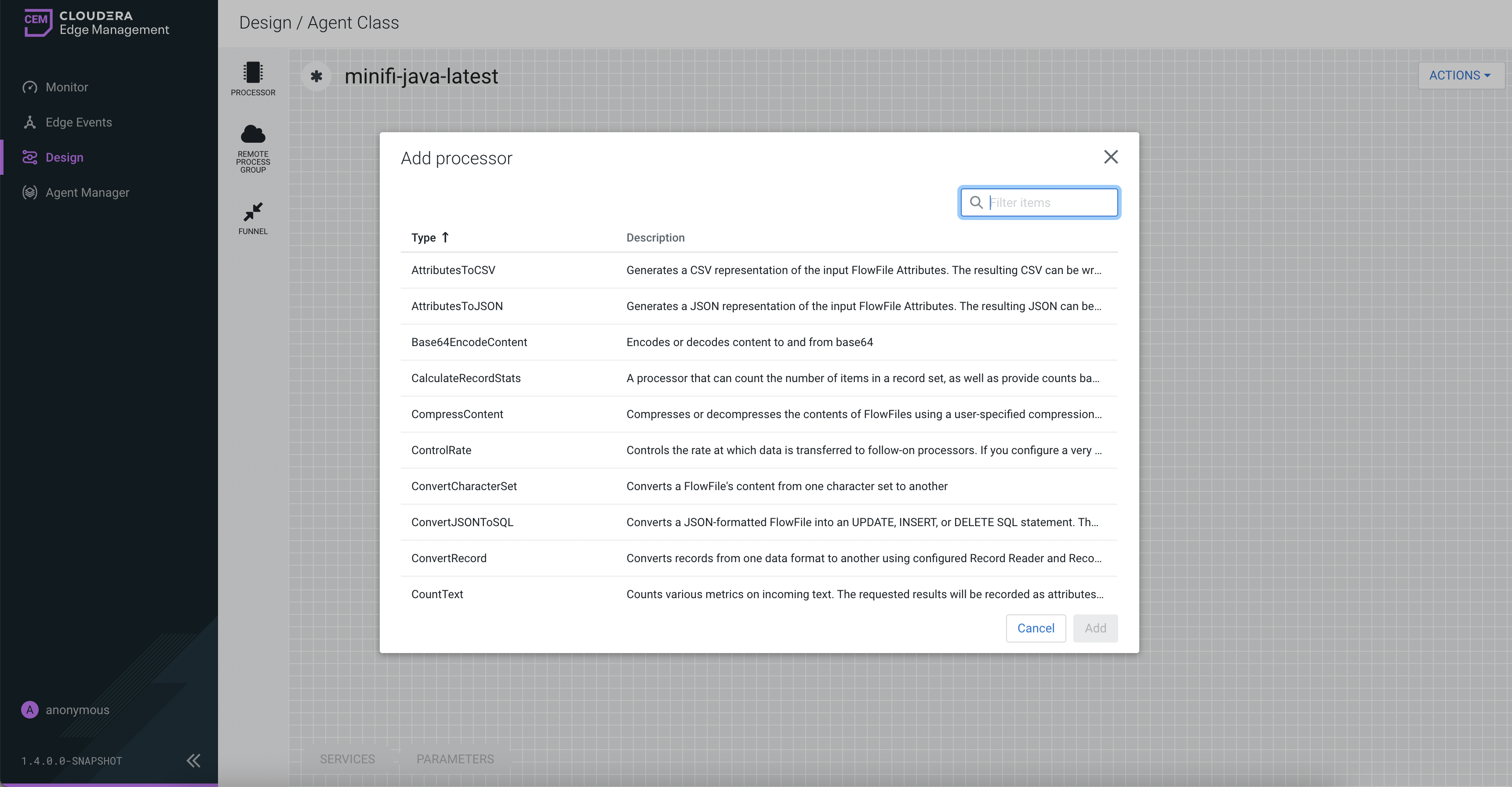
Remote process group
A Remote Process Group (RPG) references a remote instance of NiFi. When you drag an RPG onto the canvas, rather than being prompted for a name, you are prompted for the URL of the remote NiFi instance. If the remote NiFi is clustered, you need to provide at least one URL of any NiFi instance in that cluster. When data is transferred from an RPG running in MiNiFi, the RPG first connects to the remote instance whose URL is configured to determine which nodes are in the cluster and how busy each node is. This information is then used to load balance the data that is pushed to each node. The remote instances are then interrogated periodically to determine information about any nodes that are dropped from or added to the cluster and to recalculate the load balancing based on the load of each node. If the cluster node specified in the URL is down, the RPG cannot establish a connection with the cluster. To mitigate this scenario, you can enter multiple URLs, allowing the RPG to establish a connection with more than one node.
Funnel
Funnels are used to combine data from many connections into a single connection. If many connections are created with the same destination, the canvas can become cluttered if those connections have to span a large space. By funneling these connections into a single connection, that single connection can then be drawn to span that large space instead.
To delete a funnel, right-click on the funnel and select Delete from the context menu, or highlight the funnel and select DELETE on your keyboard.
Configuring a processor in Cloudera Edge Management
Learn how to configure a processor using the Edge Flow Manager UI in Cloudera Edge Management.
-
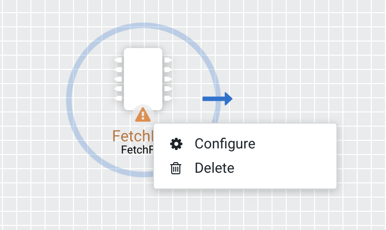
To configure a processor, right-click on the processor and select the
Configure option.
Alternatively, just double-click on the processor.The Configuration dialog opens as shown in the following image:
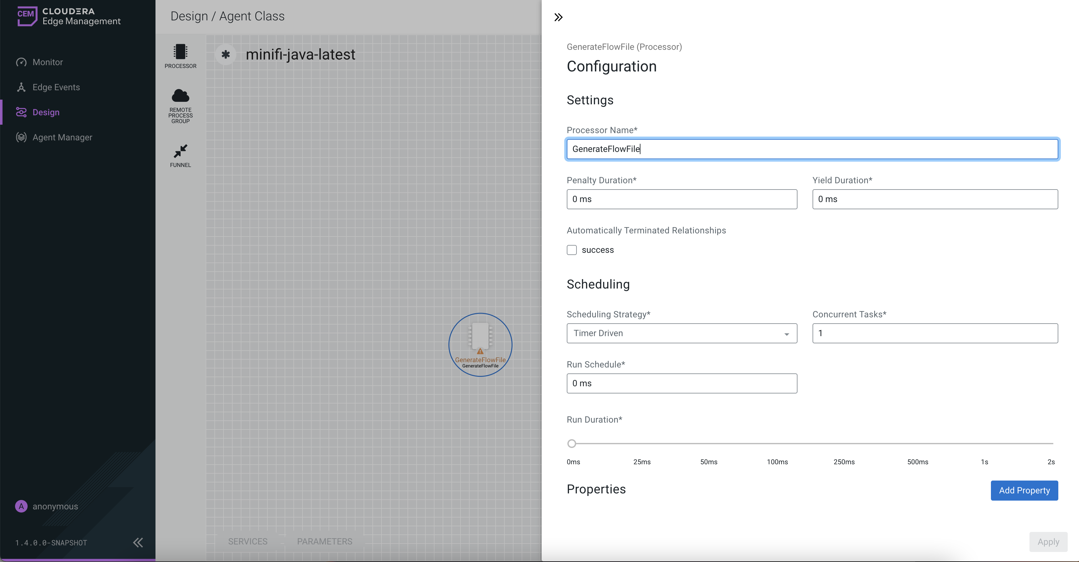
The Configuration dialog contains the following sections:
- Settings. The Settings section contains the
following configuration items:
Properties Description Processor Name Allows you to change the name of the processor. The name of a processor by default is the same as the processor type. Penalty Duration The amount of time used when a processor penalizes a FlowFile. During the normal course of processing a piece of data (a FlowFile), an event might occur that indicates that the data cannot be processed at this time but the data might be processable at a later time. When this occurs, the processor might choose to penalize the FlowFile. This prevents the FlowFile from being processed for some period of time. For example, if the processor needs to push the data to a remote service, but the remote service already has a file with the same name as the filename that the processor is specifying, the processor might penalize the FlowFile. The penalty duration allows you to specify how long the FlowFile must be penalized. The default value is 30,000 milliseconds. Yield Duration When a processor yields, the amount of time that elapses before the processor is re-scheduled is the yield duration. A processor might determine that some situation exists such that the processor can no longer make any progress, regardless of the data that it is processing. For example, if a processor needs to push data to a remote service and that service is not responding, the processor cannot make any progress. As a result, the processor must yield, which prevents the processor from being scheduled to run for some period of time. The default value is 1,000 milliseconds. Automatically Terminated Relationships Each of the relationships that is defined by the processor is listed here. In order for a processor to be considered valid, each relationship defined by the processor must be either connected to a downstream component or auto-terminated. If a relationship is auto-terminated, any FlowFile that is routed to that relationship is removed from the flow and its processing is considered as complete. - Scheduling. The Scheduling section contains
the following configuration items:
Properties Description Scheduling Strategy There are two options for scheduling components: - Timer Driven. This is the default mode. The processor is scheduled to run on a regular interval. The interval at which the processor runs is defined by the Run Schedule option (see below).
- Event Driven. When this mode is selected, the processor is triggered to run by an event, and that event occurs when FlowFiles enter connections feeding this processor. This mode is currently considered experimental and is not supported by all processors. When this mode is selected, the Run Schedule option is not configurable, as the processor is not triggered to run periodically but as the result of an event.
Concurrent Tasks This controls how many threads the processor uses or how many FlowFiles must be processed by this processor at the same time. Increasing this value allows the processor to handle more data in the same amount of time. However, it does this by using system resources that then are not usable by other processors. This essentially provides a relative weighing of processors. For example, it controls how much resources of the system must be allocated to this processor instead of other processors. This field is available for most processors. There are, however, some types of processors that can only be scheduled with a single concurrent task. Run Schedule This dictates how often the processor must be scheduled to run. The valid values for this field depend on the selected scheduling strategy (see above). When you select the Event Driven scheduling strategy, this field is not available. When you select the Timer Driven scheduling strategy, this value is a time duration specified by a number followed by a time unit, for example, 1 second or 5 mins. A value of 0 second means that the processor must run as often as possible as long as it has data to process. This is true for any time duration of 0, regardless of the time unit (for example, 0 sec, 0 mins, 0 days). Run Duration This slider controls how long the processor must be scheduled to run each time it is triggered. When a processor finishes running, it must update the repository in order to transfer the FlowFiles to the next connection. Updating the repository is expensive, so the more work that can be done at once before updating the repository, the more work the processor can handle (higher throughput). However, this means that the next processor cannot start processing those FlowFiles until the previous process updates this repository. As a result, the latency (the time required to process the FlowFile from beginning to end) becomes longer. As a result, the slider provides a spectrum from which you can choose to favor Lower Latency or Higher Throughput. - Properties. The Properties section provides a
mechanism to configure processor-specific behavior. There are no
default properties. Each type of processor must define which
properties make sense for its use case.A GenerateFlowFile processor, by default, has four properties including Batch Size, Data Format, File Size, and Unique FlowFiles. Next to the name of each property, there appears a small question-mark symbol (
 ) indicating that additional information is
available. Hovering over this symbol with the mouse provides
additional details about the property, the default value and
whether Expression Language is supported. Here is an example of
GenerateFlowFile processor with additional information for the
Batch Size property:
) indicating that additional information is
available. Hovering over this symbol with the mouse provides
additional details about the property, the default value and
whether Expression Language is supported. Here is an example of
GenerateFlowFile processor with additional information for the
Batch Size property: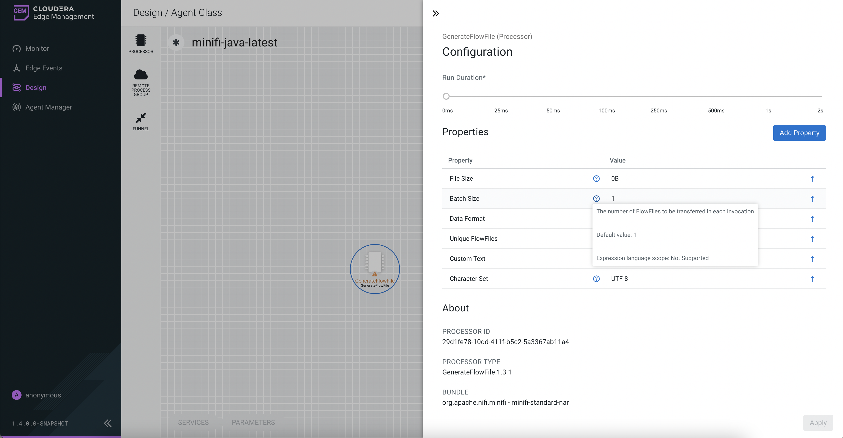
Clicking on the value for the property allows you to change the value. Depending on the values that are allowed for the property, you are either provided a drop-down from which to choose a value, or a text area to type a value. Here is an example of GenerateFlowFile processor with the drop-down for the Data Format property: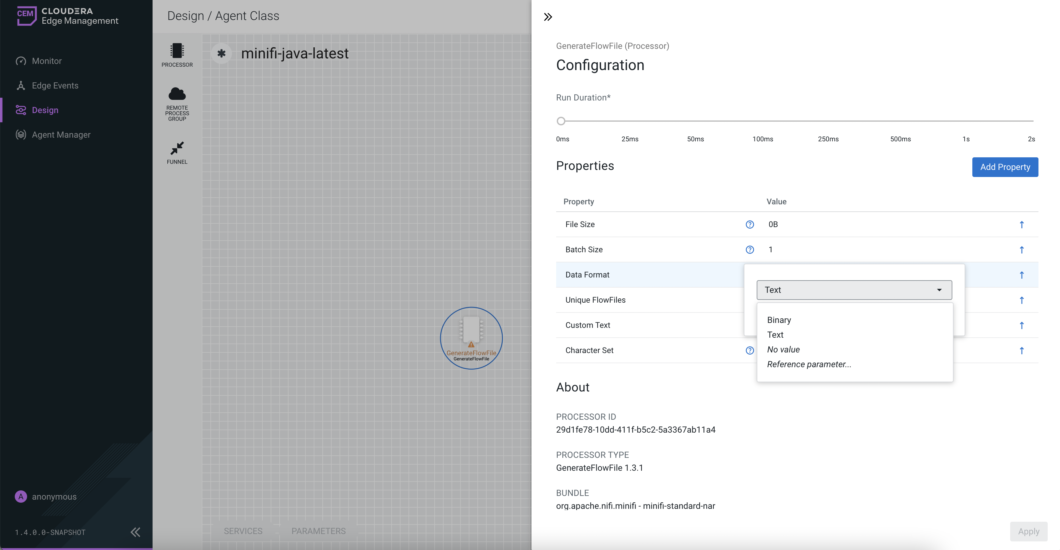
Each of the properties has an arrow in the row showing that they can be converted to parameters. The following image shows the Convert to parameter option for the Unique FlowFiles property: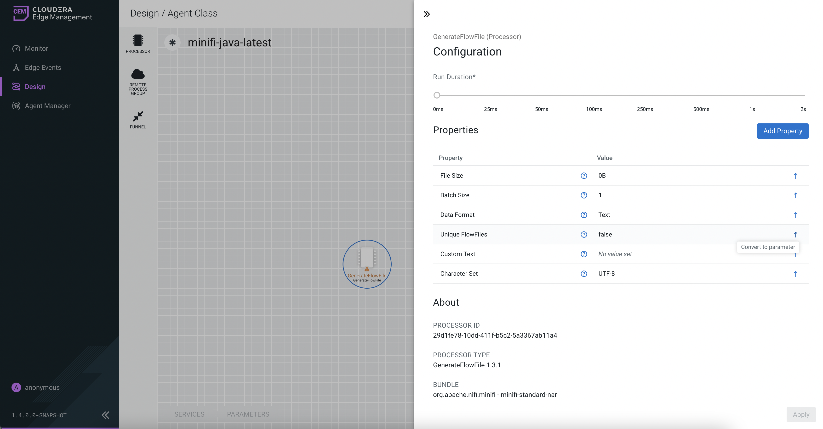
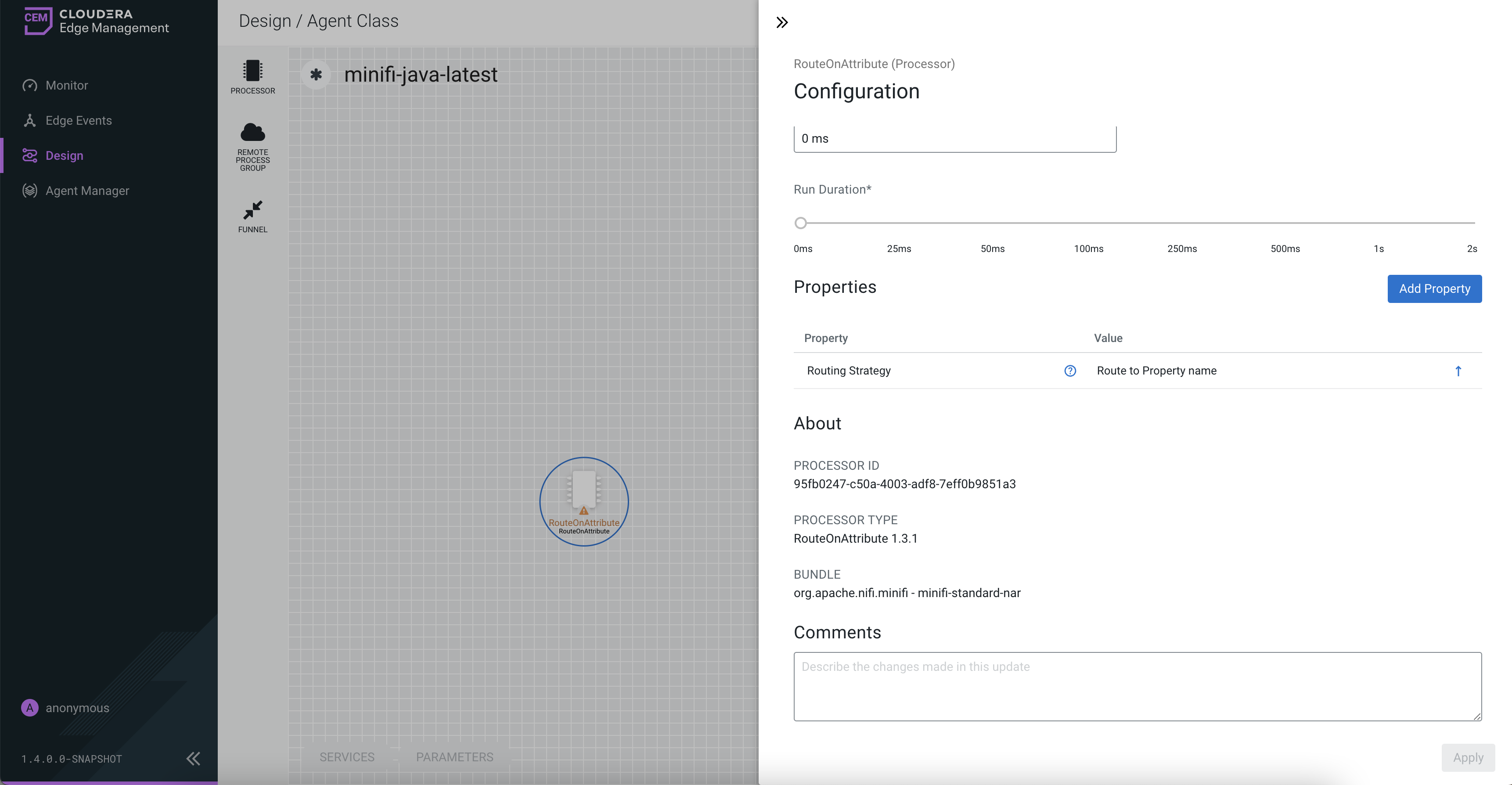
For some processors, there appears an Add Property button, beside the Properties section, for adding a user-defined property. When you click this button, a dialog opens, which allows you to enter the name and value of a new property. Not all processors allow user-defined properties. The RouteOnAttribute processor, however, allows user-defined properties. In fact, this Processor will not be valid until you add a property. The following image shows the Add Property button in the Configuration dialog of the RouteOnAttribute processor: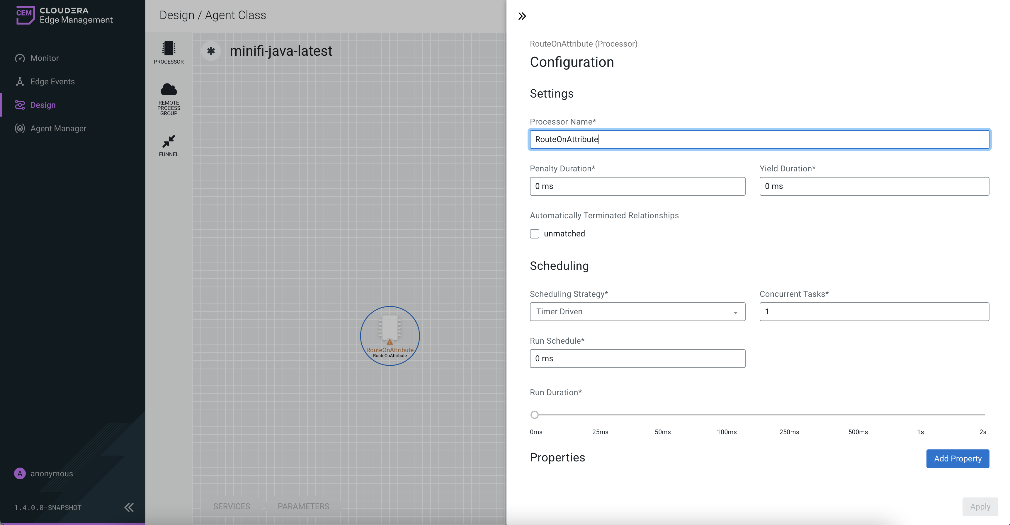
- About. The About section provides the
Processor ID, Processor Type, and Bundle details of the processor,
as shown in the following image:
- Comments. This tab simply provides an area for you to include whatever comments are appropriate for this component.
- Settings. The Settings section contains the
following configuration items:
Configuring a remote process group in Cloudera Edge Management
Learn how to configure a remote process group using the Edge Flow Manager UI in Cloudera Edge Management.
-
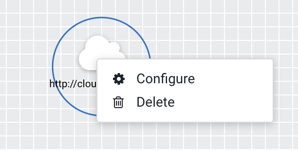
To configure an RPG, right-click on the RPG and select the
Configure option.
Alternatively, just double-click on the RPG. The Configuration dialog opens as shown in the following image:
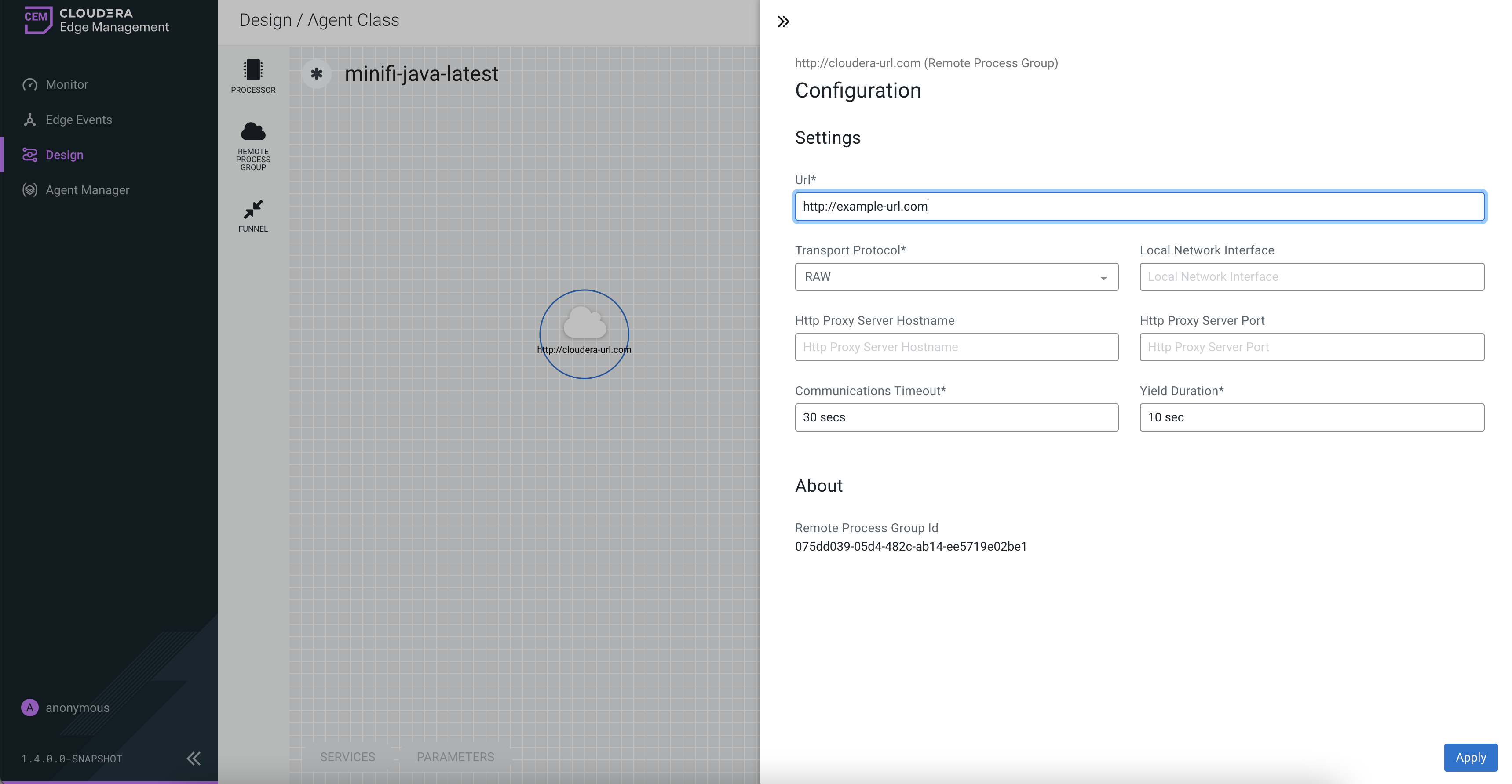
The Configuration dialog contains the following two sections:- Settings
- About. The About section provides the Remote Process Group ID.
Adding services in Cloudera Edge Management
Services are shared services that can be used by processors and other services to utilize for configuration or task execution. Learn how to add services using the Edge Flow Manager UI in Cloudera Edge Management.
-
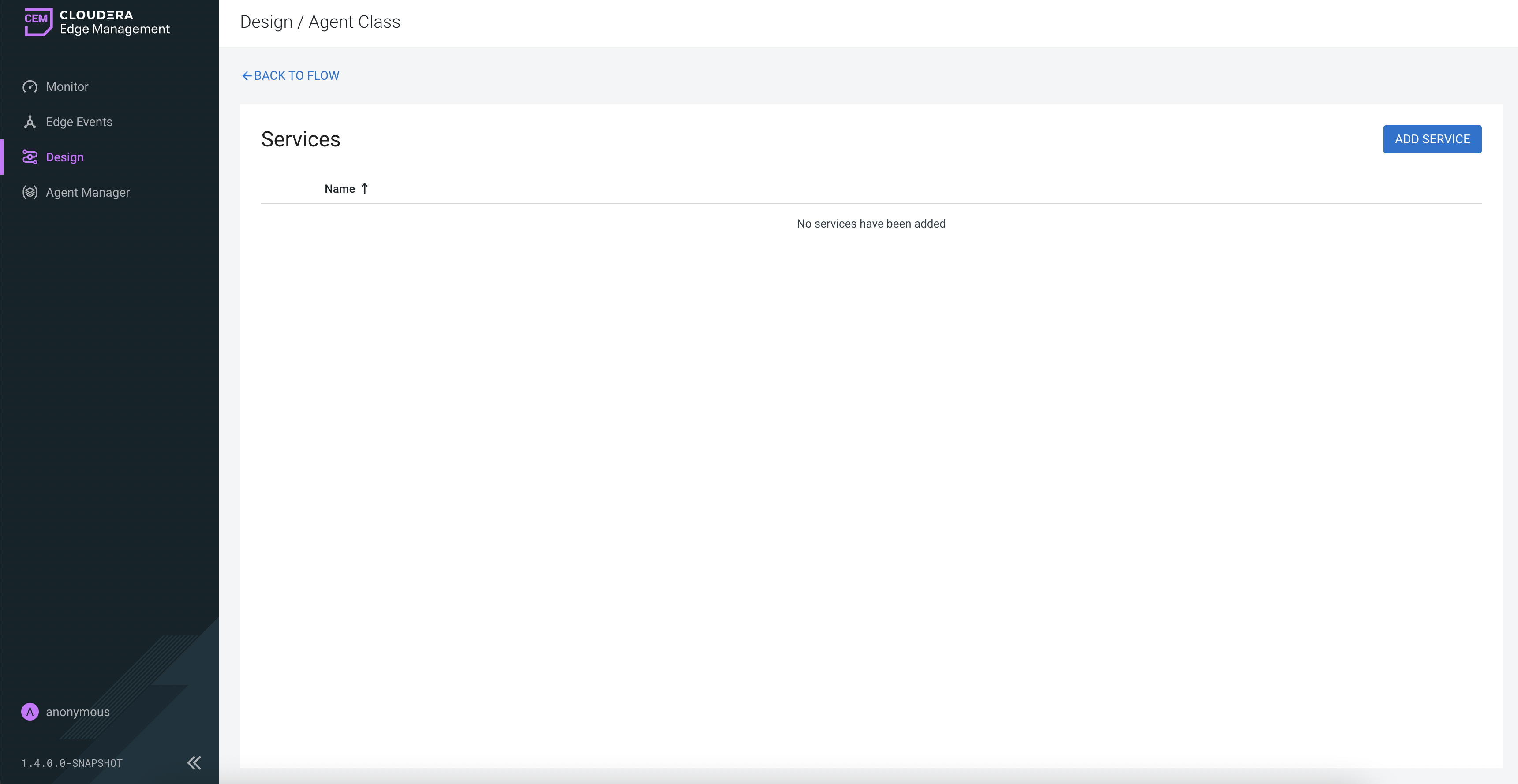
To add a service, click the SERVICES button at the
bottom-left corner of the canvas, or simply right-click on the canvas and select
Services.
The Services window opens as shown in the following image:
-
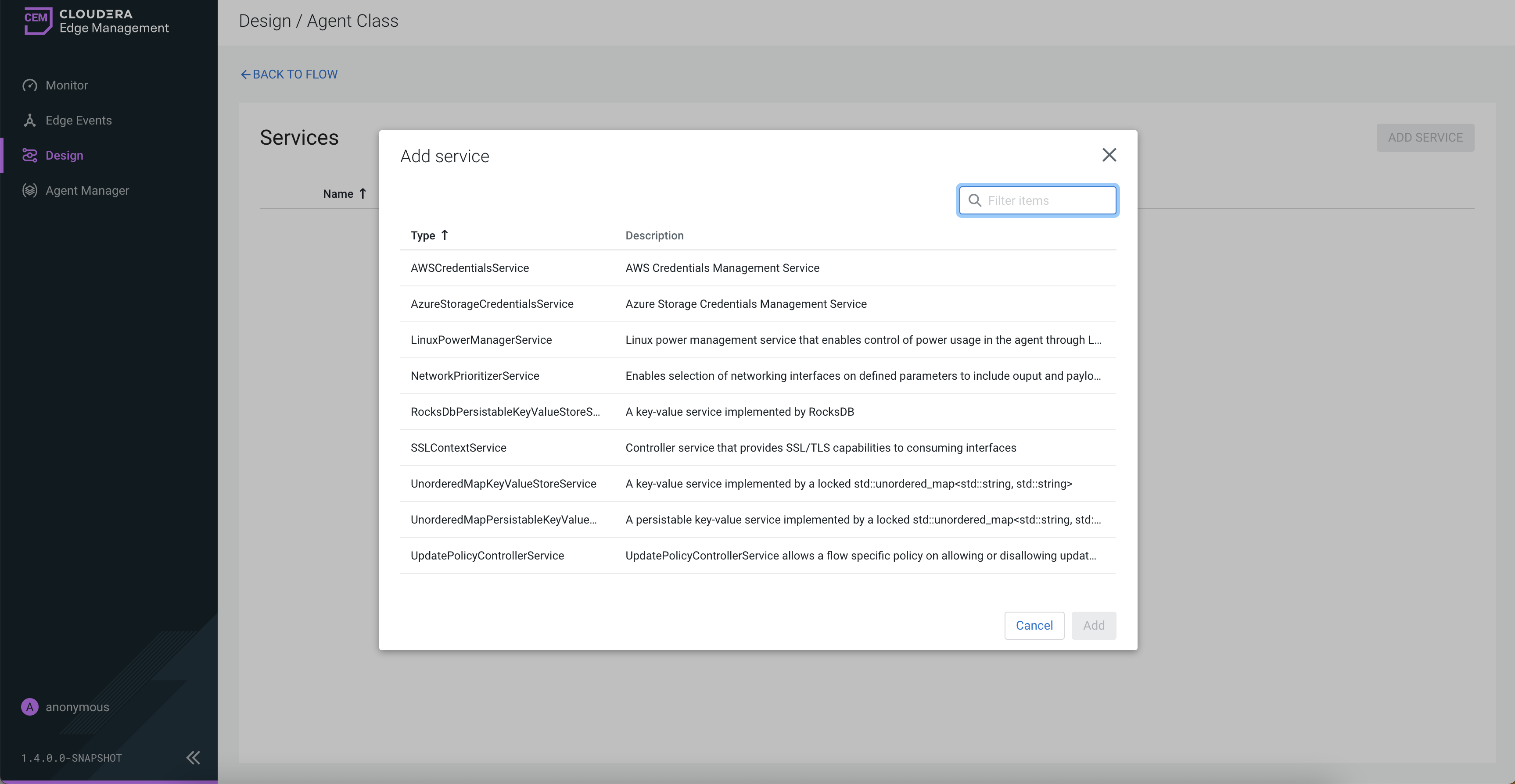
Click the ADD SERVICE button.
The Add Service dialog opens. It provides a list of the available services as shown in the following image:
-
After you add a service, configure it by clicking the
Configure icon (
 ) in the far-right
column.
The Configuration dialog opens as shown in the following image:
) in the far-right
column.
The Configuration dialog opens as shown in the following image: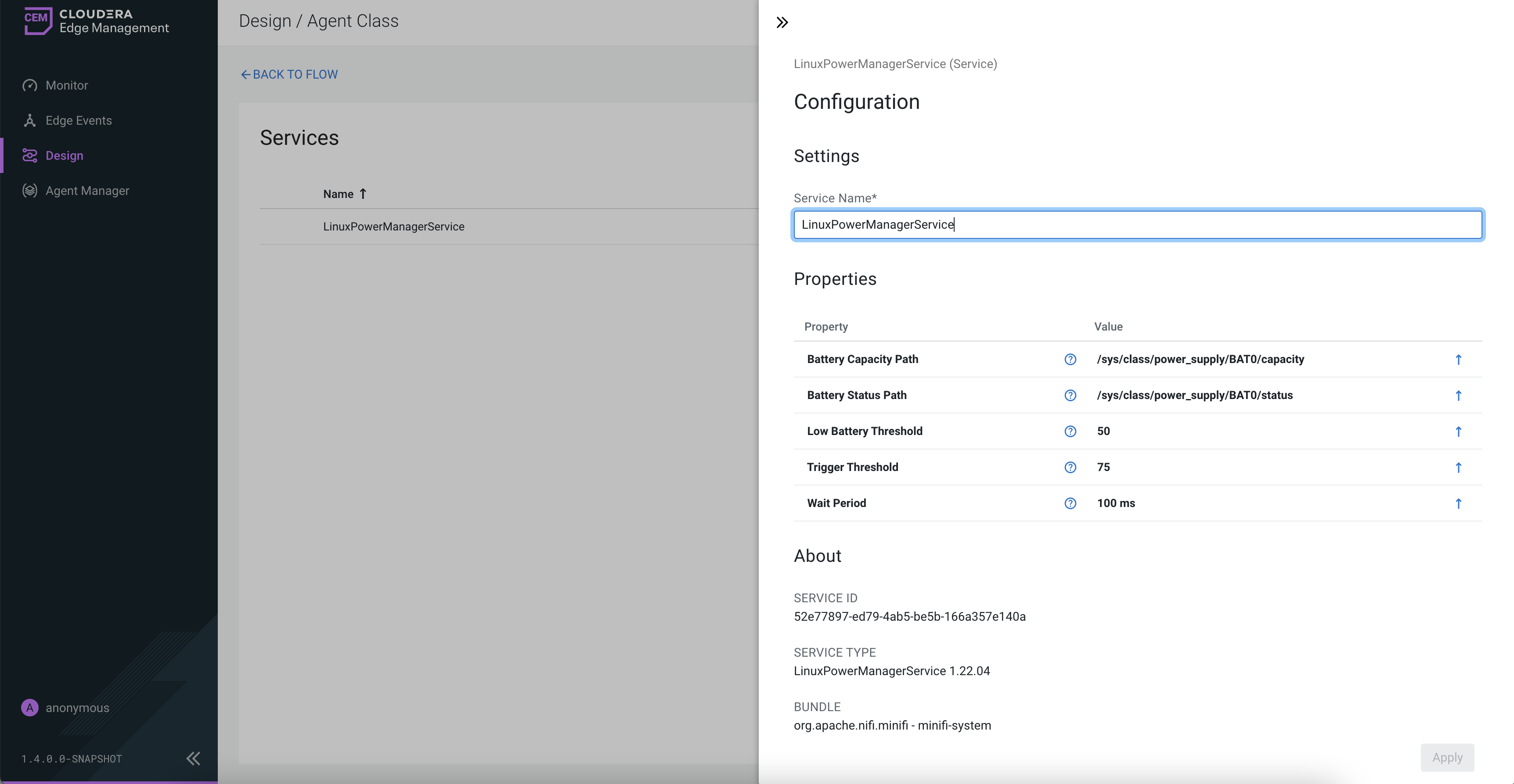
The Configuration dialog contains the following sections:- Settings. The Settings section provides a place for you to give the service a unique name. The name of a service by default is the same as the service type.
- Properties. The Properties section lists the various properties that apply to the particular service. You can hover over the question mark icons with the mouse to see more information about each property.
- About. The About section provides the Service ID, Service Type, and Bundle details of the service.
- Comments. The Comments section is just an open-text field, where you can include comments about the service.
-
After you configure a service, click the Apply button to
apply the configuration
If you want to delete a service, click the trash icon (
 ) in the far-right column. To return to the canvas, click the
BACK TO FLOW link.
) in the far-right column. To return to the canvas, click the
BACK TO FLOW link.
Connecting components in Cloudera Edge Management
After you add processors and other components to the canvas of the Edge Flow Manager UI and configure them, the next step is to connect them to one another. This is accomplished by creating a connection between each component.
-
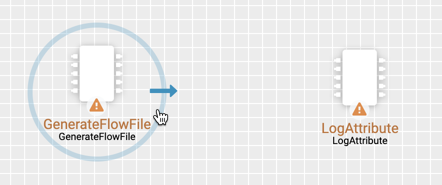
Hover the mouse over a component.
An arrow appears as shown in the following image:
-
Drag the arrow from one component to another until the second component is
highlighted, then release the mouse.
A Create Connection dialog appears as shown in the following image:
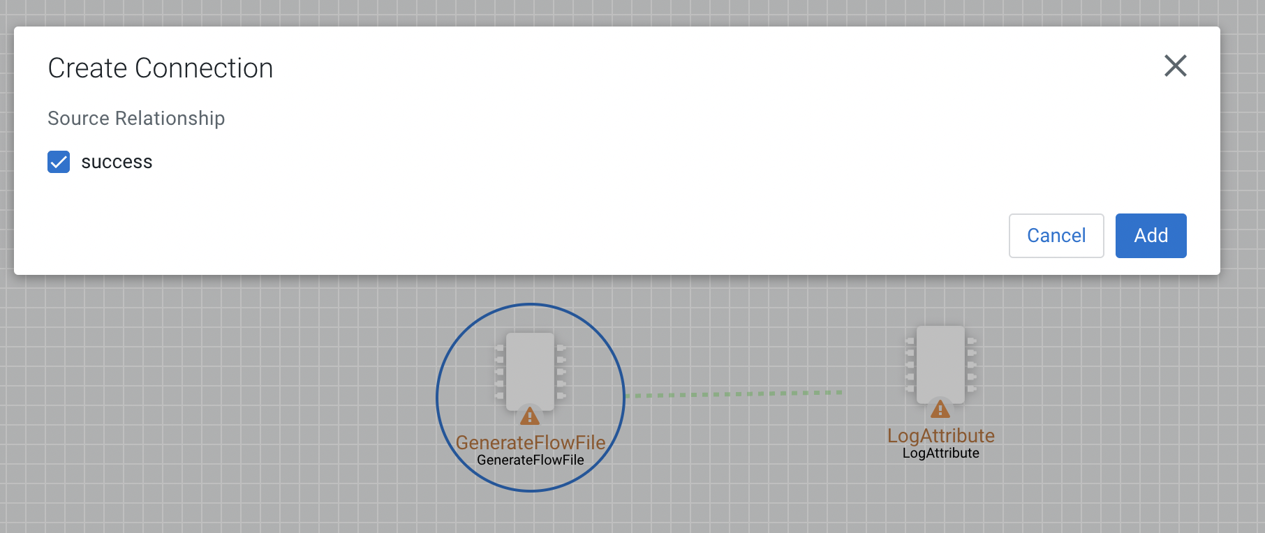
The dialog allows you to choose the Source Relationship that must be included in the connection. At least one relationship must be selected. If only one relationship is available, it is automatically selected.
Configuring a connection in Cloudera Edge Management
After you create a connection, you can change the configuration properties of the connection or move the connection using the Edge Flow Manager UI in Cloudera Edge Management.
-
To change the configuration of a connection, right-click on the connection and
select the Configure option, or double-click on the
connection.
The Configuration dialog opens as shown in the following image:
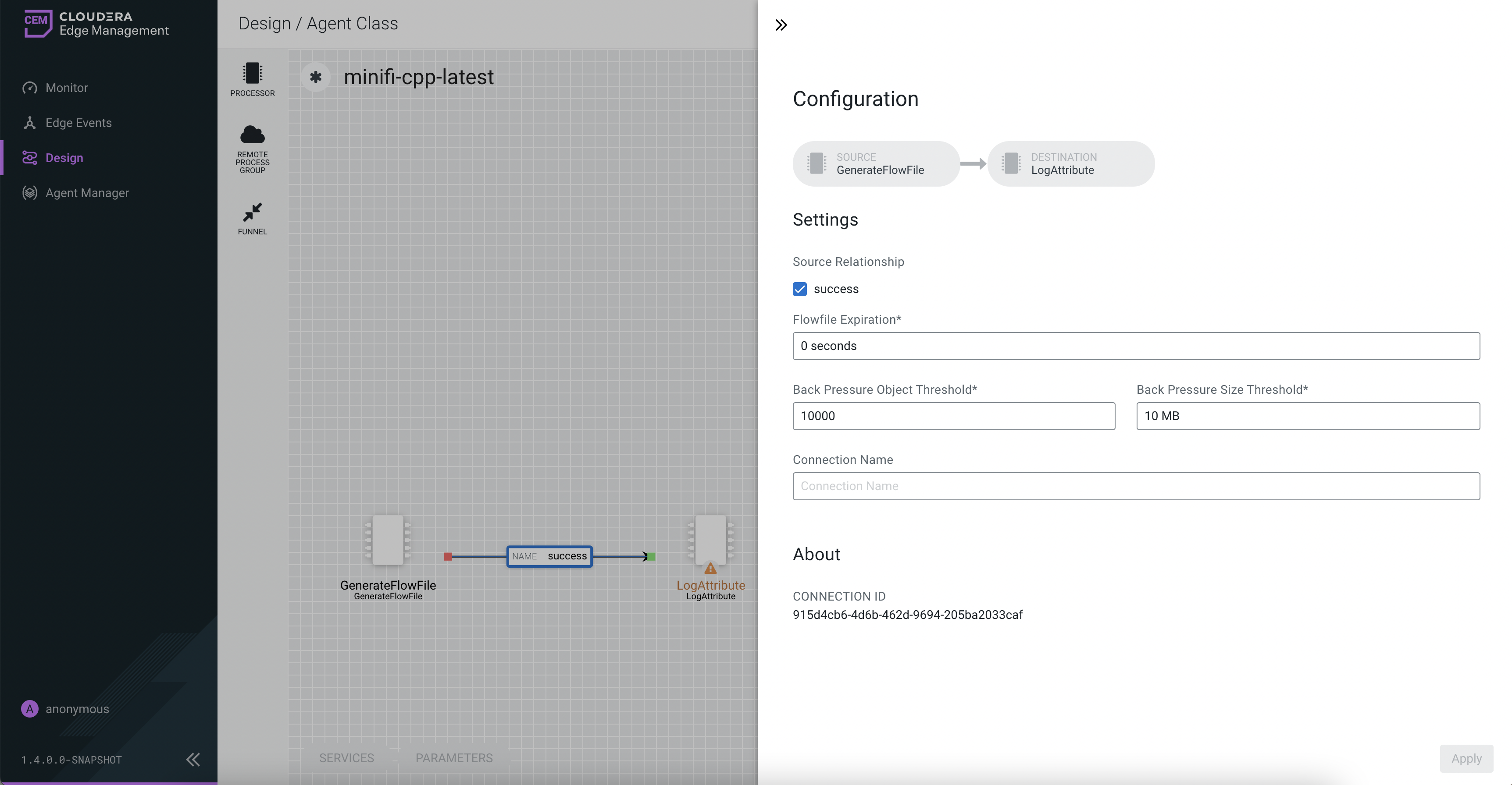
The Configuration dialog contains the following two sections:- Settings
- About. The About section provides the Connection ID.
Bending connections in Cloudera Edge Management
Learn how to bend a connection using the Edge Flow Manager UI in Cloudera Edge Management.
-
Use the mouse to grab the bend point and drag it so that the connection is bent
in the desired way.
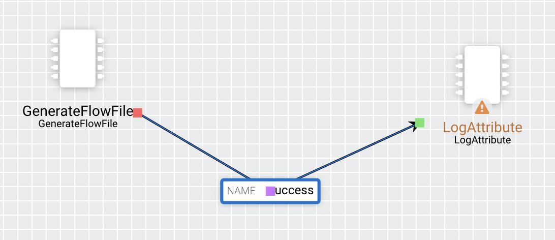
The following image shows a bend point in the connection between GenerateFlowFile and LogAttribute processors:
You can add as many bend points as you want. You can also use the mouse to drag and move the label on the connection to any existing bend point. To remove a bend point, simply double-click on it again.