Generic Reference Architecture for Cloudera Enterprise Running in a Private Cloud
About Cloudera Enterprise
Cloudera is an active contributor to the Apache Hadoop project and provides an enterprise-ready, 100% open-source distribution that includes Hadoop and related projects. The Cloudera distribution bundles the innovative work of a global open-source community, including critical bug fixes and important new features from the public development repository, and applies it to a stable version of the source code. In short, Cloudera integrates the most popular projects related to Hadoop into a single package that is rigorously tested to ensure reliability during production.
Cloudera Enterprise is a revolutionary data-management platform designed specifically to address the opportunities and challenges of big data. The Cloudera subscription offering enables data-driven enterprises to run Apache Hadoop production environments cost-effectively with repeatable success. Cloudera Enterprise combines Hadoop with other open-source projects to create a single, massively scalable system in which you can unite storage with an array of powerful processing and analytic frameworks—the Enterprise Data Hub. By uniting flexible storage and processing under a single management framework and set of system resources, Cloudera delivers the versatility and agility required for modern data management. You can ingest, store, process, explore, and analyze data of any type or quantity without migrating it between multiple specialized systems.
Cloudera Enterprise makes it easy to run open-source Hadoop in production:
Accelerate Time-to-Value
- Speed up your applications with HDFS caching
- Innovate faster with pre-built and custom analytic functions for Cloudera Impala
Maximize Efficiency
- Enable multi-tenant environments with advanced resource management (Cloudera Manager + YARN)
- Centrally deploy and manage third-party applications with Cloudera Manager
Simplify Data Management
- Data discovery and data lineage with Cloudera Navigator
- Protect data with HDFS and Apache HBase snapshots
- Easily migrate data with NFSv3 support
See Cloudera Enterprise for more detailed information.
Executive Summary
This document is intended to capture guidelines towards leveraging virtualized infrastructure (IaaS) upon which Cloudera Enterprise Clusters can be deployed. The focus of this document is around sizing and design patterns, independent of the underlying technology. This document is agnostic of specifics such as hypervisor, private cloud software, storage or networking infrastructure.
After reading this document, it is our expectation that customers and partners can build infrastructure following the guidelines provided to support deployment of Cloudera Enterprise on virtualized infrastructure.
Target Audience and Scope
This reference architecture is aimed at Datacenter, Cloud, and Hadoop architects who will be deploying Cloudera’s Hadoop stack on private cloud infrastructure.
Specifically, this document articulates design patterns that involve two distinct flavors of virtualized CDH deployment —
- Virtualized with Direct Attached storage (Shared-nothing)
- Virtualized with Remote Block storage (Converged)
Reference Architecture
Why Virtualize?
There are many reasons to virtualize infrastructure in the data center. This is a trend that has been ongoing since at least the past ten years or so. Most enterprise applications have specific and intermittent peaks in terms of utilization, and that results in extended periods of time when the hardware on which these applications run remains idle. In many cases, even during peak utilization one finds that only 15-20% of the resources of a node are actually being used. As a result, in order to improve resource utilization and provide better return on investment, virtualization took off as a technology.
However, as the community and practice matured, more benefits became apparent.
- Increased Agility
- Higher Flexibility
- Faster Time to market
- Higher Multi-tenancy
Cloudera’s customers too have been looking for these advantages, in order to better serve their internal lines of businesses, bringing public cloud-like agility to their data centers. While in the past, our reference architectures have either been in collaboration with specific partner products or technologies that had significantly large footprints, we now have enough empirical data to provide customers and partners with this generic guide that addresses topics such as sizing, network design and so on, agnostic of the underlying platform or technology.
A key factor in enabling this has been the Cloudera Enterprise Storage Device Acceptance Criteria Guide, which provides customers and partners with a baseline for acceptable storage performance criteria.
Design Patterns
In context of virtualized infrastructure (IaaS) based deployments, this document covers the two design patterns listed below.
- Virtualized with Direct attached storage - This involves deploying Virtual nodes with storage physically located on its hypervisor/host OS.
- Virtualized with remote storage - This involves deploying virtual nodes with storage located remote to its hypervisor/host OS.
Before delving into the specific design patterns, some basic concepts should be explored.
What is the purpose of a Hadoop cluster? The Hadoop ecosystem has many components that are designed to do functions varying from querying complex data structures to machine learning, but the underlying workload, when taking a reductionist approach boils down to two aspects —
- IO — Write and read large volumes of data to and from storage.
- Compute — Perform computations based on the data.
Two patterns emerge from the IO component of the workload.
- Write lots of data intermittently to the underlying storage and read that data with far greater frequency. The data is written and read in an ordered fashion. This type of workload is categorized as sequential IO.
- Read and write random, small chunks of data very fast. This type of workload is categorized as random IO.
The two storage products within the Cloudera ecosystem that address these two workloads are HDFS for Sequential IO and Apache Kudu which provides a balance between reasonable sequential and random IO.
Kudu is designed to operate very well within the parameters that govern HDFS1, with the caveat that faster storage (NVMe or SSDs) to accelerate writes (Write Logging) be leveraged.
With that in mind, we should look at sizing a cluster with HDFS capacity and throughput in mind. The majority of Hadoop ecosystem components will fit into that model.
The topic of sizing the clusters is a complex one, and while we can provide generic outlines towards sizing, the process is something that should be explored with systems engineers during an actual customer engagement. Accurate sizing requires an understanding of the specific workloads and use-cases. The following section will provide an outline that will provide scientific estimates in terms of infrastructure requirements, which can then be fine-tuned during a pre-sales engagement with Cloudera Systems Engineers.
For a more detailed discussion of the various components within the Cloudera Enterprise stack, please review the Cloudera Generic Bare-metal Reference Architecture.
1By this we mean that the storage being used for HDFS can be leveraged for Kudu as well. The same drives that back HDFS can be used for Kudu as well.
Cluster Sizing
Minimum and Recommended Performance Characteristics
This section is augmented by the Sizing Methodology section presented later in this document. This can be used to derive network throughput requirements, following a different approach than that taken in the sizing section. Per the Cloudera Enterprise Storage Device Acceptance Criteria Guide, the minimum supportable throughput per Worker node (irrespective of whether VM or Bare-metal) is 200MB/s. This implies that at least 4 gbps of East-West network bandwidth is available to the node, for proper performance.
| Minimum per-VM throughput (MB/s) | Minimum Network throughput (Gbps) | Recommended Throughput per VM (MB/s) | Recommended Network throughput (Gbps) |
|---|---|---|---|
| 200 | 4 | 800 | 16 |
The minimum throughput per Master node is, 120MB/s. The table below shows the minimum and recommended.
| Minimum per-VM throughput (MB/s) | Minimum Network throughput (Gbps) | Recommended Throughput per VM (MB/s) | Recommended Network throughput (Gbps) |
|---|---|---|---|
| 120 | 2 | 240 | 4 |
These parameters than can be utilized to build the infrastructure that supports VMs that provide these minimum characteristics. For more details, refer to the guide referenced earlier.
Cluster Sizing Methodology
Sizing the infrastructure can be approached in two different ways.
The first approach is to build the underlying infrastructure based on HDFS capacity required, while at the same time ensuring that the clusters will be well balanced between performance and capacity.
Once the physical infrastructure has been sized, then it can be converted into a private cloud and VMs built to fit as required. We call this the Build for Capacity approach.
The other approach is to consider a minimum throughput per core and the aggregate throughput needed for the cluster, which would then define the details about number of cores, network bandwidth, storage bandwidth (and therefore number of spindles/LUNs). We call this the Build for Need approach.
These two approaches help address two different scenarios. In cases where only the required HDFS capacity is known, the “Build for Capacity” approach will help size the private cloud so that it delivers a reasonable medium of both performance as well as capacity, in terms of storage, network, and compute resources.
The “Build for Need” approach will be more applicable where the required throughput of a workload is known, has better defined SLAs, etc. The virtual infrastructure can then be sized and the private cloud built.
The ‘Build for Capacity’ Approach
To summarize, in terms of formulae that can be reused, let us articulate the key determinants first.
- UC (HDFS Capacity required/Usable Capacity)
- RC (HDFS Raw Capacity)
- CT (Cluster throughput)
- PND (Number of Drives per node)
- PDC (Per drive capacity)
- PDT (Per Drive throughput)
- NBW (Network Bandwidth)
- NC (Number of Cores)
- CPS (Cores per Socket)
- NS (Number of Sockets)
- SPN (Sockets per Node)
- NN (Number of Nodes)
- STPN (Storage throughput per Node)
- SCPN (Storage Capacity per Node)
- PCT (Per-core Throughput)
- RT (Required Throughput)
Storage-based Sizing Formulae
RC = UC x 42
NN = (RC / ( PND x PDC)) + 33
NBW = PND x PDT x 8 x 24
CT = PND x NN x PDT
SPN = 2 (assumption)5
NS = NN x SPN
CPS = 10 (assumption)
NC = NS x CPS
Working through an example —
Following requirements are available —
- Usable HDFS capacity required is 400TB
- Standard hardware model in datacenter calls for 2-socket boxes with 10 Cores each.
- Standard 4TB SATA drives are used, with 12 drives per node.
- Minimum 128GB RAM per node.
UC = 400TB
CPS = 10 cores
PDC = 4 TB
PND = 12 drives
PDT =100MB/s (good estimate for SATA drives)
RC = UC x 4 = 1600TB
NN = (RC/(PND x PDC)) + 3 = (1600TB/(12x4TB)) + 3 = 37 nodes (rounded)
NBW = PND x PDT x 8 x 2 = 12 x 100MB/s x 8 x 2 = 19200Mbps (~ 20 Gbps)
NS = NN x NS = 37 nodes x 2 sockets = 74 sockets
NC = NS x CPS = 74 x 10 cores = 740 cores
CT = PND x NN x PDT = 12 drives x 37 nodes x 100MB/s = 44,400MB/s
This gives us the following blanket size to start a configuration with —
- 37 nodes - 34 Workers + 3 Masters
- Each node with 2 x 10-Core sockets and 128GB RAM
- Each node with 20Gbps NICs (pair of 10GbE NICs bonded)
- This cluster would theoretically provide about 1.6PB of raw capacity, or ~ 400TB of usable HDFS capacity. It would also generate ~ 44GB/s of sequential IO throughput.
- This cluster would have ~ 740 Physical CPU cores or 1480 Hyper-threaded CPU cores.
2This assumes the standard HDFS replication factor of 3. Add to that the 25% raw storage for intermediate storage, gives us the number 4.
3Here the number 3 represents the minimum number of Master nodes
4Here 8 is the factor that converts B/s to b/s (Bytes to bits) and 2 is factoring in 2x network bandwidth recommended for best performance
5Here assuming standard 2-socket servers are being considered. This value will change if a more compute heavy node is selected.
The ‘Build for Need’ Approach
Throughput-based Sizing Formulae
NC = RT/PCT
CPS = 10 (assumption)
NS = NC/CPS
SPN = 2 (assumption)
NN = NS/SPN
NBW = (RT x 8 x 2) / NN
STPN = RT / NN
Working through an example with this --
PCT = 50MB/s(assumption)
RT = 20GB/s (based on requirements)
NC = RT/PCT = 20GBps/50MBps = 400
NS = NC/CPS = 400/10 = 40
NN = NS/SPN = 40/2 = 20
NBW = (RT x 8 x 2) / NN = (20GBps x 8 x 2) / 20 = 16Gbps
STPN = RT / NN = 20GBps / 20 = 1 GBps
In this exercise, we start with the requirement that the cluster needs to provide 20GB/s of throughput, and expected per core throughput is 50MB/s.
Certain other assumptions are made, such as each node would have two sockets each with ten cores.
We arrive at a basic envelope size —
Certain other assumptions are made, such as each node would have two sockets each with ten cores.
We arrive at a basic envelope size --
- Require 400 cores or 40 sockets, which results in 20 physical nodes.
- The network bandwidth required to achieve the 50MB/s per core throughput is 16Gbps, or two 10GbE NICs bonded together (or a single 25Gbps NIC).
- This doesn’t do a good job of HDFS capacity sizing, but if we follow the assumption that we would require enough storage spindles to achieve 20GBps of IO throughput, we would
require at least 1 GBps of throughput per node.
- This can help derive the number of spindles per node (either Direct attached or Remote) provided we know the throughput per spindle.
- For example, if we use Direct attached SATA drives and each drive can provide 100MB/s of throughput6, we would need 10 such spindles to provide 1GBps throughput.
- If we use remote block storage, with each spindle providing say 40MB/s of throughput, we would need 25 such spindles (LUNs). That could call for more VMs to be deployed if a per-VM throughput limitation is in place.
- This would also allow the derivation of infrastructure details such as, the type of SAN HBA (Host Bus Adapter) that would be needed. 1GBps is 8 gbps, which implies 2 x 8 gbps FC Adapters could be used for fault tolerance, better load balancing across multiple paths and so on (two SAN fabrics are the norm in most shops).
- The capacity of the storage would have to be calculated based on HDFS capacity required for the cluster.
- This can help derive the number of spindles per node (either Direct attached or Remote) provided we know the throughput per spindle.
6This is typically on the lower end for SATA spindles. It is not unusual to get up to 120MB/s of sequential IO.
7This point was considering mainly the backend spindle count. In shared storage arrays, the L1 and L2 caches can easily be overrun by hadoop workloads. Typically in SAN topologies, network bandwidth is not the concern. Due to the need for multiple (typically 2 for fault tolerance) fabrics, there is sufficient capacity built in. In case of Fiber Channel, 2 x 8 gbps is standard, 2 x 16 gbps more prevalent these days and if using iSCSI, 2 x 10 gbps is the norm.
Network Topology Considerations
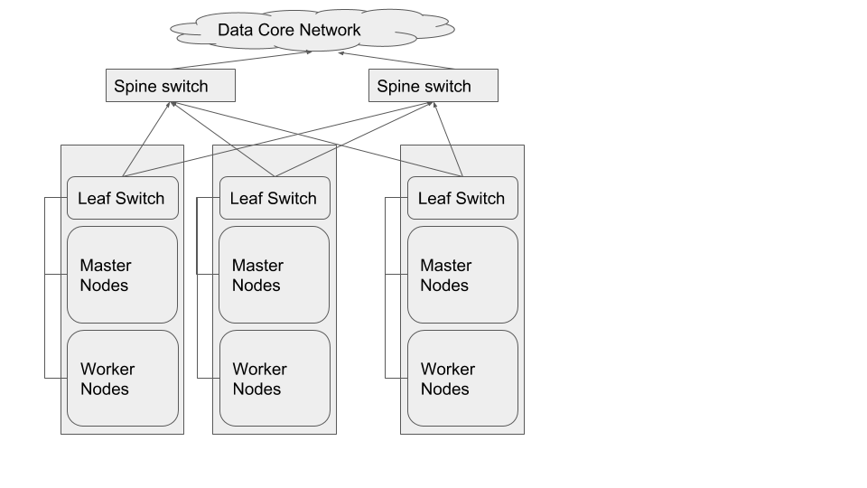
The preferred network topology is spine-leaf with no more than 4:1 oversubscription8 between leaf and spine switches, ideally aiming for no oversubscription9.
Let us step through an example scenario to better understand this. Assuming that this is a greenfield setup:
- The cluster comprises of 40 worker nodes (VMs), each with 5 SATA drives.
- This implies that the ideal IO throughput (for planning) of the cluster would be ~ 20GB/s, and a per-VM throughput of 500MB/s.
- This is the equivalent of 8 Gbps of network throughput per VM (2 x 500 MB/s x 8)
- This infrastructure could be built with 20 2-socket nodes each with 20 Gbps of network bandwidth and 10 SATA drives (for data).
The best network topology for Hadoop clusters is spine-leaf. Each rack of hardware has its own leaf switch and each leaf is connected to each spine switch. Ideally we would not like to have any oversubscription between spine and leaf. That would result in having full line rate between any two nodes in the cluster. However, beyond a certain size in clusters (more than 500 nodes), having up to 4:1 oversubscription is acceptable, since the cost of maintaining 1:1 oversubscription gets higher as a cluster scales to greater than 500 nodes.
The choice of switches, bandwidth, and other networking equipment would be predicated on the calculations in the previous section.
If we are to build the desired network topology based on the sizing exercise from above, we would need the following.
| Network Per-port Bandwidth | Number of Ports required | Notes |
|---|---|---|
| 25 | 37 | Per sizing exercise, we needed 20 Gbps per node. However, to simplify the design, let us pick single 25 gbps ports instead of bonded pair of 10gbps per node. |
Assuming all the nodes are 2 RU in form factor, we would require 3 racks to house this entire set up, and leave enough room for growth.
If we place the nodes from each layer as evenly distributed across the 3 Racks as we can, we would end up with following configuration.
| Rack1 | Rack2 | Rack3 |
|---|---|---|
| Spine ( 18 x 100 gbps uplink + 2 x 100 gbps to Core) | Spine (18 x 100 gbps uplink + 2 x 100 gbps to Core) | |
| ToR (12 x 25 gbps + 6 x 100 gbps uplink) | ToR (12 x 25 gbps + 6 x 100 gbps uplink) | ToR (13 x 25 gbps + 6 x 100 gbps uplink) |
| 1 x Master | 1 x Master | 1 x Master |
| 11 x Worker | 11 x Worker | 12 x Worker |
So that implies that we would have to choose ToR or Leaf (Top of Rack) switches that have at least 13 x 25 gbps ports and 6 x 100 gbps uplink ports. Also the Spine switches would need at least 20 x 100 gbps ports.
Using six 100 gbps uplinks from the leaf switches would result in almost 1:1 oversubscription ratio between leaves (up to 13 x 25 Gbps ports) and the spine ( 3 x 100 gbps per spine switch).
Mixing the Workload and Storage nodes in the way shown below, will help localize some traffic to each leaf and thereby reduce the pressure of N-S traffic (between Workload and Storage clusters) patterns.
8Going over 4:1 oversubscription results in bottlenecks in E-W traffic patterns, which in turn end up impacting performance of the cluster overall.
9While it is ideal to have no oversubscription, there are practical limitations that determine its feasibility, such as budget, existing physical space, and so on.
Defining the IaaS Architecture
Virtualization Design Details
Hypervisor Definition
This section defines two types of hypervisors and what is involved in their selection.
| Node Type | CPU | Memory | Storage | Network |
|---|---|---|---|---|
| Worker | As sized10 | As sized | Storage - Single virtual disk per physical disk, locally attached or remote block storage with appropriate SAN adapters (bandwidth, etc.) | Non-SDN11 |
| Worker | As sized | As sized | WL - RAID5 of multiple locally attached disks or remote block storage | Non-SDN |
10“As Sized” here is predicated on a sizing exercise undertaken, or at least based on the recommendations provided in Cloudera’s Hardware Requirements Guide.
11The SDN and Non-SDN demarcation has to do with leveraging the physical networking with minimal virtualization overhead. With SDN features enabled, such as using VXLAN, there is a encapsulation-decapsulation penalty to be paid at the network layer, and that may negatively impact performance.
Instance Type Definition
| Instance Name/Type | vCPUs | Memory | Root Disk | Additional Storage |
|---|---|---|---|---|
| cdh-worker | >=8 or as sized12 | >= 32GB or as sized | 400GB | N x Storage Volumes |
| cdh-master | 16 | >=64GB | 400GB | N x Master Volumes |
12“As Sized” here is predicated on a sizing exercise undertaken, or at least based on the recommendations provided in Cloudera’s Hardware Requirements Guide.
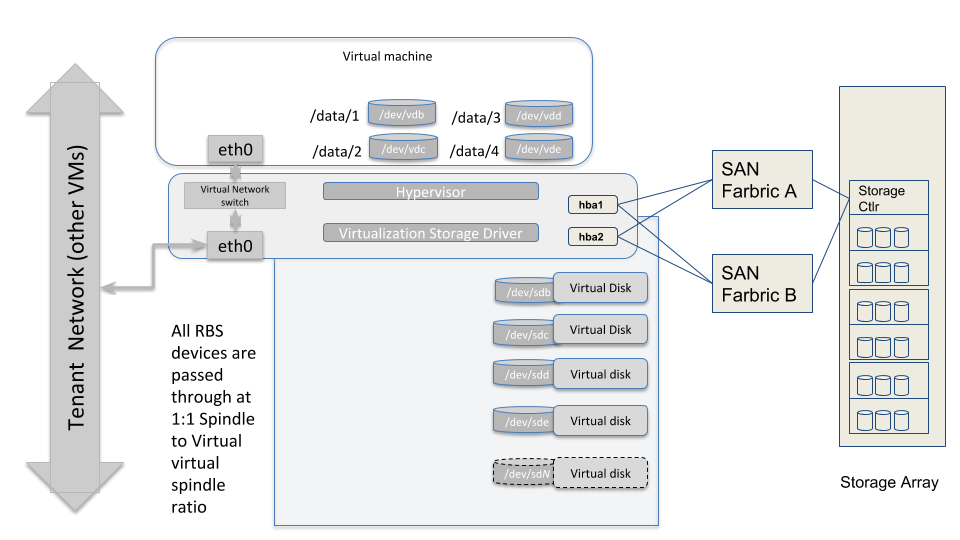
Storage Architecture
DAS Nodes
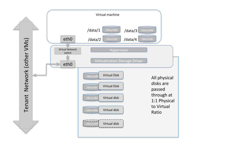
The diagram above illustrates how the storage subsystem of a worker-type node should be designed. The best practice is to obtain hardware with directly attached storage, and pass those devices through to the virtual machines running in this environment with a physical to virtual ratio of 1:1. So each physical spindle at the hypervisor level, maps to a virtual disk spindle at the VM level.
Master Nodes
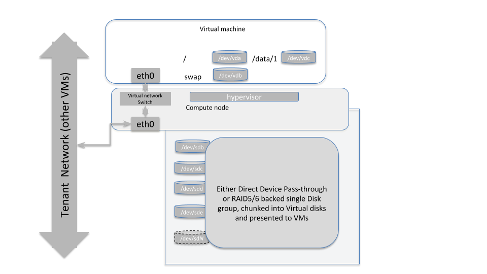
The diagram above illustrates how a master-type hypervisor system should be designed. The virtual disks provisioned on these VMs can either be Direct Device Pass-throughs as in the storage nodes, or can be a Virtual disk carved out of a RAID5/613 backed disk group (at hypervisor layer).
13The RAID level used here should be well thought through, depending on the number of spindles available at the hypervisor layer. If 6-8 disks are being used, then RAID5 or RAID6 would make sense, as they will provide both data protection as well as leverage the spindle count to provide higher throughput.
Remote Block Storage Based VMs
In SAN-based deployments there are typically two SAN fabrics, which are fault tolerant and most modern SAN HBAs can be effectively multipathed to provide load-balancing and higher aggregate bandwidth, depending on the SAN Storage Array controller (whether it is Active/Active or Active/Passive). The hypervisor layer needs to be aware of this topology and be configured to leverage best performance from the storage backend.
It is also possible to leverage more modern, distributed storage platforms, where-in drivers specific to the Software Defined Storage (SDS) system might need to be installed at the hypervisor layer. The storage then is presented to the VM layer over Ethernet/iSCSI (or similar protocols).
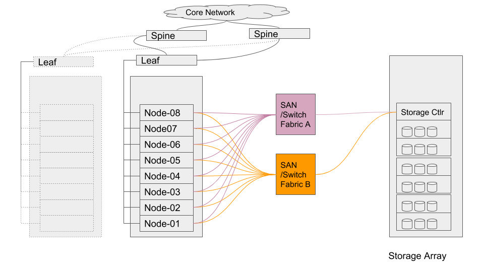
A typical SAN-based topology would resemble the diagram shown above.
With remote block storage devices (RBS) , there may not be a need for as many spindles at the VM level as we would require with locally attached storage. However, the RBS device should be able to provide adequate IO throughput to meet the minimum requirements already articulated for each type of node (masters and workers). And also, it would be operationally prudent to maintain a 1:114 mapping of RBS device to virtual storage device.
Moreover, attention must be paid to running stress tests on the infrastructure as articulated in the Storage Acceptance Guide, such that a baseline be established showing that the minimum performance characteristics are being achieved when running workloads in a distributed manner. Such tests should be run at regular intervals to ensure that acceptable SLAs are being maintained by the underlying infrastructure as clusters evolve in their compute needs or as data volumes and data velocities grow.
14This makes troubleshooting storage hotspotting etc easier to track. Maintaining a 1:1 relationship between LUN and Virtual device ensures that device mappings don’t span Guest VM boundaries.
Cloudera Software Stack
Guidelines for installing the Cloudera stack on this platform are nearly identical to those for bare-metal. This is addressed in Cloudera’s Product Documentation.
Do not allow more than one replica of an HDFS block on any particular physical node. This is enabled with configuring the Hadoop Virtualization Extensions (HVE).
The minimum requirements to build out the cluster are:
- 3x Master Nodes (VMs)
- 5x Worker Nodes (VMs)
The Worker Node count depends on the required size of HDFS storage to deploy. The following document identifies service roles for different node types — Recommended Cluster Hosts and Role Distribution.
Follow the guidelines in the Virtualization design details section to provision instance types.
- Ensure that CPU and Memory resources are not overcommitted while provisioning these node instances on the virtualized infrastructure.
- Automated movement of VMs must be disabled. There should be no Migration/Live Migration of VMs allowed in this deployment model.
- Master Nodes should be provisioned on disparate physical hardware; if possible configure them in separate physical racks or configure anti-affinity between the Master node VMs so they cannot be colocated on the same VM server..
Enabling Hadoop Virtualization Extensions (HVE)
Referring to the HDFS-side HVE JIRA (HADOOP-8468), the following are considerations for HVE:
- VMs on the same physical host are affected by the same hardware failure. In order to match the reliability of a physical deployment, replication of data across two virtual machines on the same host should be avoided.
- The network between VMs on the same physical host has higher throughput and lower latency and does not consume any physical switch bandwidth.
Thus, we propose to make Hadoop network topology extendable and introduce a new level in the hierarchical topology, a node group level, which maps well onto an infrastructure that is based on a virtualized environment.
The following diagram illustrates the addition of a new layer of abstraction (in red) called NodeGroups. The NodeGroups represent the physical hypervisor on which the nodes (VMs) reside.
Topology diagram 5
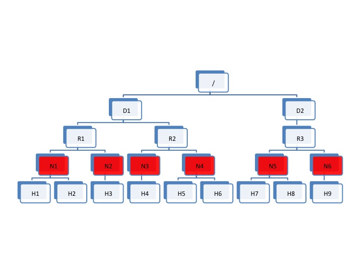
All VMs under the same node group run on the same physical host. With awareness of the node group layer, HVE refines the following policies for Hadoop on virtualization:
Replica Placement Policy
- No duplicated replicas are on the same node or nodes under the same node group.
- First replica is on the local node or local node group of the writer.
- Second replica is on a remote rack of the first replica.
- Third replica is on the same rack as the second replica.
- The remaining replicas are located randomly across rack and node group for minimum restriction.
Replica Choosing Policy
The HDFS client obtains a list of replicas for a specific block sorted by distance, from nearest to farthest: local node, local node group, local rack, off rack.
Balancer Policy
- At the node level, the target and source for balancing follows this sequence: local node group, local rack, off rack.
- At the block level, a replica block is not a good candidate for balancing between source and target node if another replica is on the target node or on the same node group of the target node.
HVE typically supports failure and locality topologies defined from the perspective of virtualization. However, you can use the new extensions to support other failure and locality changes, such as those relating to power supplies, arbitrary sets of physical servers, or collections of servers from the same hardware purchase cycle.
Using Cloudera Manager, configure the following in safety valves:
- HDFS
- hdfs core-site.xml (Cluster-wide Advanced Configuration Snippet (Safety Valve) for core-site.xml/core_site_safety_valve):
<property>
     <name>net.topology.impl</name>
<value>org.apache.hadoop.net.NetworkTopologyWithNodeGroup</value>
</property>
<property>
     <name>net.topology.nodegroup.aware</name>
     <value>true</value>
</property>
<property><name>dfs.block.replicator.classname</name><value>org.apache.hadoop.hdfs.server.blockmanagement.BlockPlacementPolicyWithNodeGroup</value></property>
- hdfs core-site.xml (Cluster-wide Advanced Configuration Snippet (Safety Valve) for core-site.xml/core_site_safety_valve):
- In mapred-site.xml, add the following properties and values (this is set using the HDFS Replication Advanced configuration snippet (safety valve) mapred-site.xml
(mapreduce_service_replication_config_safety_valve)):
<property>
 <name>mapred.jobtracker.nodegroup.aware</name>
 <value>true</value>
</property>
<property><name>mapred.task.cache.levels </name><value>3</value></property>
Establish the Topology:
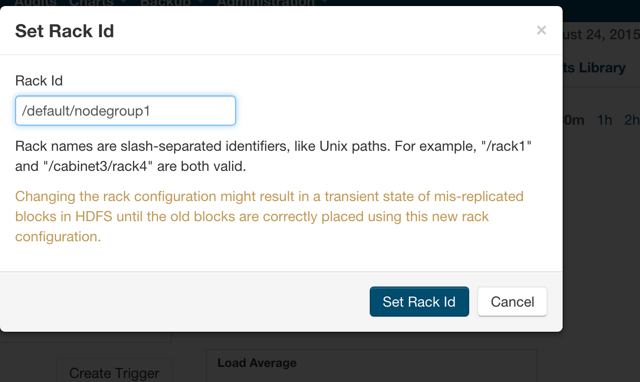
Follow the instructions to set rack location of hosts here — Specifying Racks for Hosts.
Select all multiple hosts from the Hosts page and then assign rack.
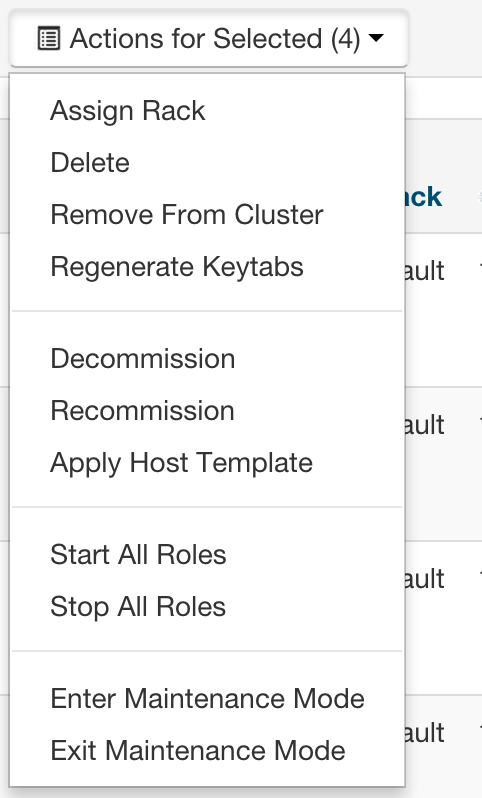
Alternately, In Cloudera manager, you can specify the topology by going into the Hosts/Status page and editing the Rack assignment from /default to /default/nodegroup<id>.
Instructions
The following safety valves need to be applied --
- HDFS -- Cluster-wide Advanced Configuration Snippet (Safety Valve) for core-site.xml
- YARN - YARN Service MapReduce Advanced Configuration Snippet (Safety Valve) - mapred.xml
Follow this sequence of actions to enable HVE —
- Apply the safety valves
- Assign the rack topology to the nodes
- Stop the cluster
- Deploy client config
- Start ZooKeeper
- Start HDFS
Start all other services.
References
Glossary of Terms
| Term | Description |
|---|---|
| CDH | Cloudera Distributed Hadoop |
| Ceph | An open-source distributed storage framework (RADOS or Reliable Autonomic Distributed Object Store) that allows a network of commodity hardware to be turned into a shared, distributed storage platform. Ceph natively provides Block Storage (RBD or RADOS Block Device) that are striped across the entire storage cluster, an Object Store as well as a shared filesystem. |
| CM | Cloudera Manager |
| CMA | Cloudera Manager Agent |
| DataNode | Worker nodes of the cluster to which the HDFS data is written. |
| Cloudera EDH | Cloudera Enterprise Data Hub |
| Ephemeral Storage | Storage devices that are locally attached to Nova instances. They persist guest operating system reboots, but are removed when a Nova instance is terminated. |
| HBA | Host bus adapter. An I/O controller that is used to interface a host with storage devices. |
| HDD | Hard disk drive. |
| HDFS | Hadoop Distributed File System. |
| HA/High Availability |
Configuration that addresses availability issues in a cluster. In a standard configuration, the NameNode is a single point of failure (SPOF). Each cluster has a single NameNode, and if that machine or process became unavailable, the cluster as a whole is unavailable until the NameNode is either restarted or brought up on a new host. The secondary NameNode does not provide failover capability. High availability enables running two NameNodes in the same cluster: the active NameNode and the standby NameNode. The standby NameNode allows a fast failover to a new NameNode in case of machine crash or planned maintenance. |
| HVE | Hadoop Virtualization Extensions - this is what enables proper placement of data blocks and scheduling of YARN jobs in a Virtualized Environment wherein, multiple copies of a single block of data or YARN jobs (don’t get placed/scheduled on VMs that reside on the same hypervisor host). The YARN component of HVE is still work in progress and won’t be supported in CDH 5.4 and above (YARN-18). The HDFS component is supported in CDH 5.4 and above. |
| JBOD | Just a Bunch of Disks (this is in contrast to Disks configured via software or hardware RAID with striping and redundancy mechanisms for data protection) |
| JHS/Job Server History | Process that archives job metrics and metadata. One per cluster. |
| LUN | Logical unit number. Logical units allocated from a storage array to a host. This looks like a SCSI disk to the host, but it is only a logical volume on the storage array side. |
| NN/NameNode | The metadata master of HDFS essential for the integrity and proper functioning of the distributed filesystem. |
| NIC | Network interface card. |
| Node Manager | The process that starts application processes and manages resources on the DataNodes. |
|
QJM QJN |
Quorum Journal Manager. Provides a fencing mechanism for high availability in a Hadoop cluster. This service is used to distribute HDFS edit logs to multiple hosts (at least three are required) from the active NameNode. The standby NameNode reads the edits from the JournalNodes and constantly applies them to its own namespace. In case of a failover, the standby NameNode applies all of the edits from the JournalNodes before promoting itself to the active state. Quorum JournalNodes. Nodes on which the journal services are installed. |
| RM | ResourceManager. The resource management component of YARN. This initiates application startup and controls scheduling on the DataNodes of the cluster (one instance per cluster). |
| SAN | Storage area network. |
| SPOF | Single Point of Failure |
| ToR | Top of rack. |
| VM/instance | Virtual machine. |
| ZK/ZooKeeper | ZooKeeper. A centralized service for maintaining configuration information, naming, and providing distributed synchronization and group services. |
