Learn about the recommended deployment topology for your Cloudera Base on premises cluster that allows each host to maximize
throughput and minimize latency, while encouraging scalability.
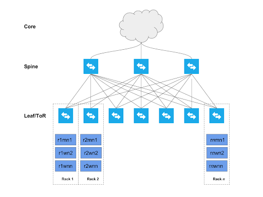
The following graphic shows a cluster deployed across several racks (Rack 1, Rack 2, … Rack n).
Each host is connected to two top-of-rack (TOR) switches which are in turn connected to a
collection of spine switches which are then connected to the enterprise network. This deployment
model allows each host to maximize throughput and minimize latency, while encouraging
scalability. The specifics of the network topology are described in the subsequent sections. The
nomenclature represents the rack number, the role of a node in the cluster, and its ordinality in
the rack. For example: r1mn1 would represent Rack1, Master Node 1, and so on. Every rack need not
have a master node. It is a good practice to spread all master nodes of a cluster across
different racks to avoid single point of failure. Gateway and utility nodes also reside within
these racks (not annotated in the diagram).